|
|
|
|
|
|
|
The Power in Water The power available in a flow of water over a given interval depends on two factors: the vertical distance the water "falls" over the interval, measured in feet or meters, and the volume of the flow of water, measured in cubic feet or cubic meters per second.
The Hydro Power Equation For an estimate of the power available in a given stream or river, the following formula may be used: power = 10 x flow x fall x efficiency where "power" is measured in kilowatts, "flow" in cubic meters per second, and "fall" in meters. Efficiency includes that of the turbines and the generators. Friction losses in the system are usually factored into the equation by decreasing the "fall" variable by an appropriate amount. 1 meter =~ 39 inches Components of a Small Hydro System
Feeder Canal Water flows down the feeder canal from the intake to the forebay. The canal is usually made of earth or concrete, and is fitted with a grating to keep out solid objects carried by the stream. Forebay The forebay is a tank that holds water between the feeder canal and the penstock. It must be deep enough to ensure that the penstock inlet is completely submerged so that air is excluded from the power equipment. Penstock The penstock is a pipe connecting the forebay to the power house. It pressurizes the water and must be capable of withstanding high pressures, and is therefore made of steel or high-density plastic. Power House The power house stores and protects all the power-producing equipment and control devices. These devices can be operated and monitored either on site or remotely. Tail Race The tail race is the flow of water out of the power house back into the stream. Reserve Power Hydro-electric plants are designed to use only part of the total water flow under normal operating conditions. The reserve flow is the portion of the flow not normally used. Intake The intake is a buffer between the water supply and the hydro-electric plant. It is constructed of earth, masonry, concrete, or riprap. It's shape is largely determined by the nature of the terrain. Fish Ladder The fish ladder allows salmon to migrate upstream to minimize the biological impact of the power plant. Hydro Energy Production Equipment:
Generators must conform to characteristics of the electrical equipment they are powering. Control systems act to modify the water flow to the turbine to maintain the desired characteristics (A), or to dissipate excess energy (B).
Generators
Small Hydro Case Studies: Washington State, US
Small Hydro Case Studies: Washington State, US
Small Hydro Case Studies: Hydro-electric
Power Hydro-electric power is electricity produced by the movement of fresh water from rivers and lakes. This water comes to the rivers as runoff from rainfall. Rainfall is powered by by solar energy which drives complex energy transfer processes in the atmosphere and between the atmosphere and the oceans. The potential (gravitational) energy associated with this water causes it to flow downwards. This downward motion of water contains kinetic energy, that can be converted into mechanical energy, and then from mechanical energy into electrical energy in hydro-electric power stations. ("Hydro" comes from the Greek word hydra, meaning water). At a good site hydro-electricity can generate very cost effective electricity. History and Development The conversion of kinetic energy into mechanical energy is not a new idea. As far back as 2000 years ago wooden waterwheels were used to convert kinetic energy into mechanical energy. The exact origin of water wheels is not known, but the earliest reference to their use comes from ancient Greece. However, it was much later, in 1882 in the United States, that the first hydro-electric plant was built. This plant made use of a fast flowing river as its source. Some years later, dams were constructed to create artificial water storage areas at the most convenient locations. These dams also controlled the water flow rate to the power station turbines. Originally, hydro-electric power stations were of a small size and were set up at waterfalls in the vicinity of towns because it was not possible at that time, to transmit electrical energy over great distances. The main reason why there has been large-scale use of hydro-electric power is because it can now be transmitted inexpensively over hundreds of kilometres to where it is required, making hydro-power economically viable. Transmission over long distances is carried out by means of high voltage, overhead power lines called transmission lines. The electricity can be transmitted as either AC or DC. Unlike conventional coal-fired power stations, which take hours to start up, hydro-electric power stations can begin generating electricity very quickly. This makes them particularly useful for responding to sudden increases in demand for electricity by customers ("peak demand"). Hydro-stations need only a small staff to operate and maintain them, and as no fuel is needed, fuel prices are not a problem. Also, a hydro-electric power scheme uses a renewable source of energy that does not pollute the environment. However, the construction of dams to enable hydro-electric generation may cause significant environmental damage. How Hydro-Electric Power Stations Operate
Water
is collected and stored in the dam above the station for use when it is
required. Some dams create big reservoirs to store water by raising the levels
of rivers to increase their capacity. Other dams simply arrest the flow of
rivers and divert the water down to the power station through pipelines. While
a water turbine is much more sophisticated than the old water wheels, it is
similar in operation. In both cases blades are attached to a shaft and when
flowing water presses against the blades, the shaft rotates. (The effect is the
same as wind pressing against the blades of a windmill.) After the water has
given up its energy to the turbine, it is discharged through drainage pipes or
channels called the "tailrace" of the power station for irrigation or
water supply purposes or, in some parts of the world, even into the ocean.
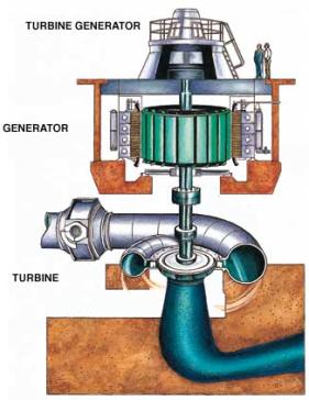
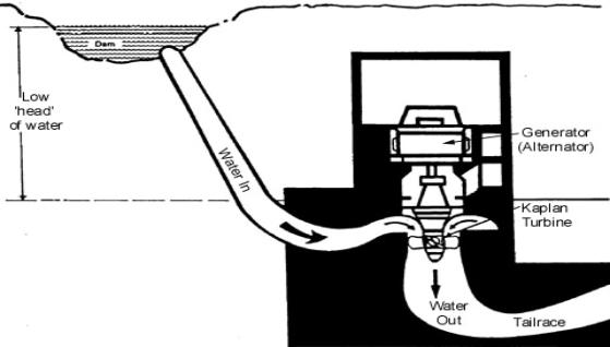
Figure
2 Cut-away drawing of a water-turbine generator (Image
courtesy of the Snowy Mountains Hydro-Electric Scheme) In
a conventional coal-fired (thermal) power station each "generating
unit" consists of a boiler, a steam turbine, and the generator itself. A
hydro-electric generating unit is simpler and consists of a water turbine to
convert the energy of flowing water into mechanical energy, and an electric
generator to convert mechanical energy into electrical energy. The
amount of energy available from water depends on both the quantity of water
available and its pressure at the turbine. The pressure is referred to the head,
and is measured as the height that the surface of the water is above the
turbine. The
greater the height (or head) of the water above the turbine, the more energy
each cubic metre of water can impart to spin a turbine (which in turn drives a
generator). The greater the quantity of water, the greater the number and size
of turbines that may be spun, and the greater the power output of the
generators. Type
of Water Turbines Water
for a hydro-electric power station’s turbines can come from a specially
constructed dam set high up in a mountain range, or simply from a river close to
ground level. As water sources vary, water turbines have been designed to suit
the different locations. The design used is determined largely by head and
quantity of water available at a particular site. The
three main types are Pelton wheels, Francis turbines, and Kaplan or propeller
type turbines (named after their inventors). All can be mounted vertically or
horizontally. The Kaplan or propeller type turbines can be mounted at almost any
angle, but this is usually vertical or horizontal. The
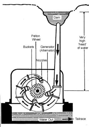
Pelton wheel (see figure 3) is used where a small flow of water is available
with a ‘large head’. It resembles the waterwheels used at water mills in the
past. The Pelton wheel has small ‘buckets’ all around its rim. Water from
the dam is fed through nozzles at very high speed hitting the buckets, pushing
the wheel around
Figure
3 Pelton wheel (Copyright
Western Power Corporation [1]) The
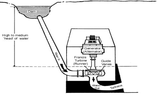
Francis turbine (see figure 4) is used where a large flow and a high or medium
head of water is involved.
Figure
4 Francis water turbine (Copyright
Western Power Corporation [1]) The
Francis turbine is also similar to a waterwheel in that it looks like a spinning
wheel with fixed blades in between two rims. This wheel is called a
‘runner’. A circle of guide vanes surround the runner and control the amount
of water driving it. Water is fed to the runner from all sides by these vanes
causing it to spin. Propeller
type turbines are designed to operate where a small head of water is involved.
These turbines resemble ship’s propellers. However, with some of these (Kaplan
turbines, see figure 5) the angle (pitch) of the blades can be altered to suit
the water flow.
Figure
5 Kaplan and propeller type turbine (Copyright
Western Power Corporation [1]) The
variable pitch feature permits the machine to operate efficiently over a range
of heads, to allow for the seasonal variation of water levels in a dam. Large
Scale Hydro Large
scale hydro-electric power systems have been installed all over the world, with
the largest having a capacity of over 10
000 megawatts (MW) (10 gigawatts (GW)). Each of these large scale systems
requires a very large dam, or series of dams, to store the enormous quantities
of water required by the system. The Kariba dam in Zambia holds 160 billion m3
of water! The
Snowy Mountains hydro-electric power scheme is the largest in Australia, with a
generation capacity of nearly 3800 MW. The Snowy Scheme consists of seven power
stations (2 underground), 145km of tunnels and 16 large dams, with the largest
Lake Eucumbene holding nine times the water volume of Sydney Harbour. Tasmania’s
Hydro-Electric Corporation generates the second largest amount of hydro power in
Australia, utilising the high rainfall and mountainous terrain of Tasmania.
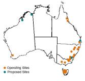
Figure
6 shows the locations of Australia's large scale hydroelectric generating
stations, which combined produce almost 7.6 GW of power. Tasmania is shown as
one large dot, due to the large number of generators in the State. Figure
6 Locations of operating and proposed hydroelectric power stations Pumped
Storage Hydro-electric Schemes A
large number of new hydro-electric projects are of the pumped storage type. Each
station re-uses the water which is passed through it, by storing it in catchment
areas below the station and then pumping it back up to the higher catchment dams
above the station in a closed circuit arrangement. This pumping is carried out
in ‘off-peak’ times when there is a surplus of power available from coal,
oil, or gas-fuelled stations to accomplish the task. In many countries nuclear
power is used for off-peak pumping. When
pumping is required, a reversal of roles occurs. The generator becomes an
electric motor, receiving electricity from a nearby power station, and operates
the turbine as a pump. The turbine receives energy instead of delivering it. However,
in some pumped-storage schemes there are two sets of equipment. One set is for
generating and the other is for pumping. The use of pumped storage increased the
total amount of power generated by the hydro power station, but this increase is
not renewable. The pumps are run by non renewable sources allowing excess
electrical energy to be stored as the potential of energy of water raised to the
height of the dam. The amount of renewable energy produced by the hydro power
station remains the same. Status
of Hydro Power Worldwide In
1994, hydro-electric power represented 2% of the world's primary energy
consumption [2]. There is currently (1998) about 700GW of installed hydro
capacity worldwide, generating about 2,600TWh (2.6 x 10¹² kWh) of electricity
per year, and producing 19% of the world’s electricity. Hydro
power supplies at least 50% of electricity production in 66 countries, and at
least 90% in 24 countries. It is estimated that only 32% of the economically
feasible hydro power potential worldwide have been developed so far [3]. The
installed hydro power capacity in Australia is 7.6GW [4]. Of this capacity, 50%
comes from the Snowy Mountains Hydro-Electric Scheme and 30% from the
Hydro-Electric Corporation of Tasmania (see figure 6).
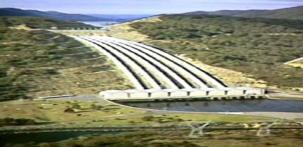
Figure
7 Photo of Tumut 3 Power Station, Snowy Mountains Copyright
Snowy Mountain Hydro-Electric Authority In
1997, Asia had an installed hydro-electric capacity of about 100GW [5]. Asia is
the continent with the fastest growing hydro-electric industry, with many Asian
countries stating that hydro power is the main focus for the development of
their power sectors. China currently has the highest level of hydro power
development activity in the world. The 18.2GW Three Gorges dam, the 3.3GW Ertan
and the 1.8GW Xiaolangdi hydro-electric projects are all under construction.
Hydro-electric schemes with a total capacity of 50GW are currently under
construction, which will double the existing capacity in the country. The
construction of an additional four large-scale projects will commence shortly:
Xiluodo (14.4GW), Xiangjiaba (6GW), Longtan (4.2GW), and Xiaowan (4.2GW). A
further 80GW of hydro power is planned, including 13 stations along the upper
reaches of the Yellow River, and 10 stations along the Hongshui River [6,7]. A
280MW hydro power station is being constructed in Paunglaung, Myanmar [7]. The
country plans to double its hydro capacity to 600MW by the year 2000 [6]. In the
Philippines, construction has started on the 70MW Bakun AC scheme, which will be
one of the first private hydro projects in the country [7]. Vietnam has a large
number of medium to large-scale hydro schemes planned for completion by the year
2010, including the 3.6GW Son La scheme. India has 10GW of hydro power under
construction, with a further 28GW planned. Indonesia has six large-scale hydro
schemes planned, with a total capacity of 2GW [6]. However, due to environmental
and economic pressures, the 2.4GW Bakun hydro-electric project has been
indefinitely delayed [7]. A
number of Asian countries have major pumped-storage development programs,
including Korea (2.3GW under construction and 800MW planned), Thailand (1GW
under construction and 1.46GW planned) and Indonesia (1GW planned) [6]. Constraints
to Large-Scale Hydro Power Use While
hydro power has benefits in terms of carbon dioxide emissions and air pollution,
it also has significant negative environmental impacts. Hydro-electric power
installations have a detrimental effect on river flows and water supplies.
Large-scale hydro schemes result in the flooding of large areas of land, often
leading to the displacement of people living in the area, and to negative
impacts on local fauna and flora. Proposed hydro power projects often face
pressure from environment and human rights groups concerned about the social and
environmental impacts of the projects, eg. the 18.2GW Three Gorges dam project
in China, the 2.4GW Bakun project in Malaysia, and the 400MW Maheshwar project
in India [7]. Small
Scale Hydro Power Hydro
power is available in a range of sizes from a few hundred watts to over 10GW. At
the low end of the spectrum, small hydro power can be divided into three
categories. The definitions of the categories vary, but are broadly: micro (less
than 100kW), mini (100kW-1MW) and small (1MW-10MW) hydro [8]. This section
focuses on micro-hydro systems, which are generally stand-alone systems, ie they
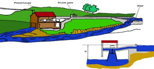
are not connected to the electricity grid. Micro-hydro
systems operate by diverting part of the river flow through a penstock (or pipe)
and a turbine, which drives a generator to produce electricity (see Fig.8). The
water then flows back into the river. Micro-hydro systems are mostly "run
of the river" systems, which allow the river flow to continue. This is
preferable from an environmental point of view as seasonal river flow patterns
downstream are not affected and there is no flooding of valleys upstream of the
system [9]. A further implication is that the power output of the system is not
determined by controlling the flow of the river, but instead the turbine
operates when there is water flow and at an output governed by the flow. This
means that a complex mechanical governor system is not required, which reduces
costs and maintenance requirements. The systems can be build locally at low
cost, and the simplicity gives rise to better long term reliability. However,
the disadvantage is that water is not carried over from rainy to dry season. In
addition, the excess power generated is wasted unless an electrical storage
system is installed, or a suitable ‘off-peak’ use is found.
Figure
8 A low-head micro-hydro installation (Image
adapted from Stockholm Environment Institute [10].) Micro-hydro
systems are particularly suitable as remote area power supplies for rural and
isolated communities, as an economic alternative to extending the electricity
grid. The systems provide a source of cheap, independent and continuous power,
without degrading the environment. It
is estimated that in 1990 there was an installed capacity worldwide of small
hydro power (less than 10MW) of 19.5GW [8]. There
are two main types of turbines used in micro-hydro systems, depending on the
flow and the head, namely impulse turbines and reaction turbines. Typical
impulse turbines are the Pelton wheel and the Turgo wheel, and these are
generally used for medium to high-head applications. Reaction turbines are
generally used at low (propeller turbine) or medium head (Francis turbine) [10]. Electrical
energy can be obtained from a micro-hydro system either instantaneously or
through a storage system. In an instantaneous power demand system, the system
provides 240V AC power to the load via a turbine which must be sufficiently
large to meet the peak power demand. These systems require a large head and/or
flow. In a storage system, the micro-hydro generator provides a constant DC
charge to a battery system, which then supplies power to the load via an
inverter. The battery system must be sized to the daily electrical demand.
However, the turbine is significantly smaller than for an instantaneous demand
system, and it operates at a constant power output. Micro-Hydro
Power in Australia
The
use of micro-hydro systems in Australia is not well documented. A number of
small micro-hydro units are available [11, 12] for domestic remote area power
supplies, tourist facilities, cathodic protection for pipe lines, and the like.
Currently (1998), the typical cost of a 20kW micro-hydro unit (excluding civil
works) is A$14,300 [11]. An example of a typical micro-hydro system in Australia
is a remote wilderness lodge in Tasmania . The installation has an effective
head of 142m and a flow rate of 46 litres/second. The 52kW generator provides
the lodge with refrigeration, 6kW of lighting, some instant heating, hot water
and small power requirements. The capital costs were A$2.5 per watt (in 1991).
However, suitable micro-hydro resources, in locations where they can be utilised,
are limited in Australia [4]. Micro-Hydro
Power in Asia Micro-hydro
installations are widespread in Asia, where there is a significant resource
potential for further development. China has a well developed hydro power
industry, with an estimated (1993) 60,000 small hydro power installations (less
than 1MW), with a combined capacity of about 17GW. The installed capacity of
micro-hydro power in Nepal is estimated to be 8.7MW. The topography of Nepal is
ideal for micro-hydro power, with high hills, scattered settlements and more
than 6,000 rivers crossing the country. It is estimated that the economically
viable micro-hydro potential in Nepal is about 42MW. The cost of stand-alone
plants is in the range of US$1,200-1,600 per kW (in 1993 dollars) [13]. The
installed small hydro power (less than 10MW) capacity in Vietnam is 61.4MW, with
an estimated potential of about 1.8GW. Some 3,000 sites have been identified for
micro-hydro installations in the range of 1kW-10kW. These sites will serve
irrigation and drainage needs, in addition to generating electricity for 2
million households. Many areas in Vietnam do not have access to the electricity
grid, due to the high extension costs. In these areas, micro-hydro units are
used by individual families for lighting and battery charging (for television
and lighting use). It is estimated that over 3,000 family units of 1kW or less
are installed in Vietnam [13]. Other
Asian countries with micro-hydro resources include Laos, Bangladesh, the
Philippines, Papua New Guinea and Indonesia. In 1998, the Indonesian government
announced its intention to electrify 18,600 villages using small and micro-hydro
schemes [6]. China aims to continue to install 1GW per year of small hydro
capacity for rural electrification [6]. The
Future for Micro-Hydro Power As
a cheap, renewable source of energy with negligible environmental impacts,
micro-hydro power has an important role to play in future energy supply
scenarios, particularly in developing countries. It is an attractive alternative
to diesel systems in rural and remote areas of developing countries as a means
of achieving rural electrification. Hydraulic
Rams/Pumps The
downward movement of water from a height can also be used to pump water. The
basic principle is that the movement of a large amount of water over a short
distance creates enough pressure to pump a small amount of water a large
distance. Devices that use this principle are called hydraulic ram pumps.
Hydraulic
Hydro Rams
/ Pumps
An
Australian inventor, Ralph Glockemann, has recently developed a pump of this
type that only requires a head of 0.5m and yet is capable of pumping water to a
height of over 200m. In the Glockemann Pump, the force of the inlet water acting
on a diaphragm is used to pump smaller amounts of water long distances. The pump
is able to use a flow rate of 4.5 litres per second and head of just 1.0m, to
pump over 1500 litres per day to a height of 100m. This form of water pumping
requires no fuel and is almost silent in operation making it much more
environmentally friendly than petrol or diesel powered pumps [15]. |
|
|
|

 The Power in Water (3)
 Gearing
 Turbines
 Environmental Impact
 Environmental Integration


![Text Box: Figure 1 Diagram of hydro-electric scheme
(Copyright Western Power Corporation [1])](tute.h25.gif)